This is an old revision of the document!
Tutorial: State-based Modeling and Test Generation
Learning Objectives
What is a State Model
State model is a directed graph consisting of nodes (states) and directed edges (transitions). A state represents the state of the system you are modeling and transition represents the event or action, when executed, changes the system's state from one to another.
For example, if we were to model a vending machine, we would use a state to represent the balance (money deposited) and use a transition to represent a coin being inserted into the machine.
For modeling a web application, we would use a state to represent each web page or popup dialog or the selection of a dropdown list, etc. and a transition to represent a button or link which when click will take us to another web page or a different select being made in the dropdown list.
A valid model must have:
- one Initial node
- one or more Final node
- one or more states
- transitions connecting nodes/states
and all states and Final nodes must be reachable from Initial node.
Create Model
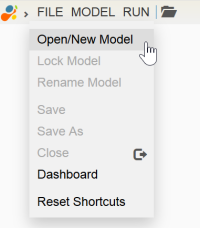
TestOptimal supports state-based model and combinatorial model. They are both created by clicking on ![]() on the toolbar or clicking on menu File / Open/New Model:
on the toolbar or clicking on menu File / Open/New Model:
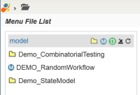
The Menu File List opens:
By default it opens at the root folder model. Navigate to the folder that you want the new model to be stored and click on ![]() to create state-based model.
to create state-based model.
Enter the model name at the New Model prompt:
If the model is created successfully, it will be added to the model list. Go ahead and click on the model name to open it. IDE opens the new model in Model Editor.
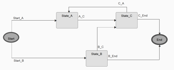
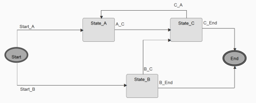
Our goal is to create a simple model that looks like the following when completed:
Add States and Transitions
States and transitions are added by selecting the appropriate icon from the toolbar and click on the modeling canvas to add states/transition to the model.
Create Initial / Final Nodes
Since a model must have one Initial node and at least one Final node. Let's create these first and place one on the left and the other on the right of the modeling canvas:
- click on left side of modeling canvas to place Initial node
- click on right side of modeling canvas to place Final node
The nodes were created with a default name, let's change them to “Start” and “End”:
- select edit mode by clicking on ★
- open Property Pane by
- double clicking on the node, or
- change the name as shown below:
You can re-position the nodes by dragging ![]() .
.
When done, close the property pane by clicking on “>” on the right side of the pane.
If needed, nodes, states and transitions can be deleted by clicking on “X” on the context menu.
Create States
To add states to the model, select the state icon ![]() from the toolbar
from the toolbar  and click on modeling canvas where you want the new state to be placed.
Let's create the three states and place them between Initial and Final nodes.
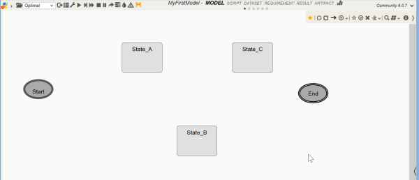
States are created with a default names, go ahead and change their names to “State_A”, “State_B” and “State_C”. Your model should look like below:
Click on ★ to switch editor to edit mode.
Create Transitions
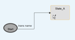
Transitions connect the source state to the target state. So you have to identify the source and target state for each transition. Furthermore, you will also need to decide which side of the source and target states you want the transition to start and ends. This involves tapping the sides of the source and target states.
To create a transition:
- select ➜ on toolbar
- click on a side of source state
- click on a side of target state
Transition consists of segments. IDE draws the appropriate segments required to connect the states without crossing over the states.
Like creating a new state, new transitions are created with default name and they can be changed through Transition Properties, which can be accessed by:
- double clicking on transition label, or
Go ahead and change their names and your model should look like below, remember to select the edit mode by clicking on ★ before you can make changes to the transition.
Arranging States and Transitions
States and transitions can be re-positioned on the model while in Edit mode.
Moving State
Moving Transition
If the transitions are not routed the way as shown above, you can change the transition routing by dragging the transition segment.
When you move the start or end segment of the transition to the adjacent side of the state, the transition will be re-routed from that side of the state.
Moving Transition Label
Transition label can also be moved: mouse over the transition label and drag on ![]() .
.
Transition label is positioned from the position of the start segment from the source state. This ensures that they are re-positioned automatically when its source state or transition start segment is moved.
Be sure to save the model changes before moving on to next.
Generate Test Cases
When model is completed, we are ready to generate test cases from it. Test cases are generated by traversing the states and transitions to achieve the desired coverage using algorithms, aka model sequencers.
For purpose of this demonstration, we'll just use the default Optimal sequencer as shown in the app toolbar  .
.
Click on ![]() on the app toolbar to generate the test cases using Optimal sequencer.
on the app toolbar to generate the test cases using Optimal sequencer.
You should see some status messages showing up on the bottom of the screen. When done, it should auto select RESULT tab like below, if not click on RESULT tab on the app header:
Explanation on RESULT tab is covered in a separate tutorial. We will just review the test cases generated in the “Test Case” section.
Model Graphs and Test Visualization
In addition to the test case list described in the previous section, you can view the test cases in graphs:
Click on each of the graphs on  .
.
The graphs should be self-explanatory.
Make Changes
As you followed this tutorial, you should have noticed that you can easily make changes to the model and re-generate test cases with minimum effort.
Here are a few more changes you can make to the model:
- aligning states by selecting (marking) states and clicking on one of the alignment options from the toolbar
- re-routing transitions with transition context menu:
- styling the states and transitions through State Properties and Transition Properties.
You may also us Box node to group or highlight a set of states.
If you are modeling a workflow or process, you can use Swimlanes to distinguish multiple different process and actor.

